I would be grateful for your help in solving an error in my coupled models.
I am still working with the coupling of CROCO and WW3. I have opted to follow the “at hand” methodology.
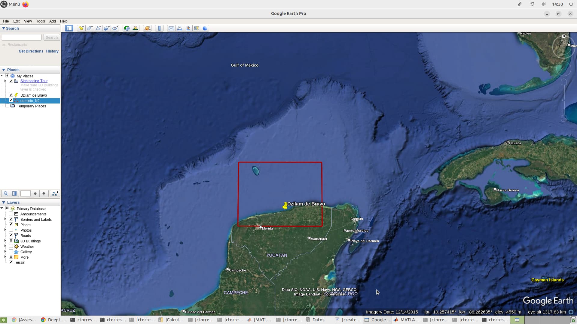
Having said that, I am running a WCI application in the northern Yucatan peninsula. My resolution is 1km. The boundary conditions for CROCO have been interpolated from a “parent” domain by off-line nesting; for WW3 I am not using boundary forcing, so they are closed boundaries.
I have identified that the error is a blow-up in CROCO on simulated day 20; I believe the error occurs on the eastern border of the domain; I have tried reducing the time steps as much as possible, but the error still occurs on exactly the same simulated day. For this reason I decided to move the eastern border a little more to the west, but the blow-up persists; this time the coupling runs a little more. In the peninsula there is a strong influence of the yucatan current, so I try to make sure that the eastern boundary of my coupled domains are not close to this strong current. Note that I have run 3 year simulations for each model separately and with larger time steps without problems.
I have uploaded to the cloud all the WCI application (including cppdefs) that I try to run (~5G). There should be no problem downloading it. Here is a link>> 5.19 GB folder on MEGA
If someone could check my application and give me some tips to fix this error I would appreciate it very much. I think I have explored all the ideas I know of to solve this error.
Please let me know if there is any more information I can provide.
Thank you, Smaishal, you are kind, I will wait for your feedback.
I have done more tests anyway, without much luck. Only when I do the coupling with a low resolution of 4 km, it seems that there are no problems, because, at least I can simulate a month.
I have a doubt in mind. Perhaps with some shame I ask it, because these are things that you take for granted that you understand them. With these problems I have in coupling with WW3, I have thought about time steps in CROCO.
The baroclinic is calculated according to:
And something that is not completely clear to me is how the baroclinic dt is defined. It is always defined as 60 barotropic time steps in one baroclinic time step.
If my grid has a spatial resolution of 1000 m and a maximum depth of ~60 m, then the barotropic dt should be 2.3 s?
And the baroclinic dt what would it be?
Well, until now I had not thought of modifying my NDTFAST. It has always been 60s. Now I have increased it to 120 just to test.
Hi Cesar, I had a look at your configuration, but first let me rectify something about the time stepping. The constraint you indicate in your post is that of the barotropic time step. Then you need to compute your baroclinic CFL according to the advection scheme you use, as it is explained in this page of the doc : 9. Running the model — Croco Doc 2.0.1 documentation.
You can change NDTFAST of course (which, by the way, is not a number in seconds but a number of barotropic time steps inside one baroclinic time step).
Looking at your croco_grd.nc file, I can see that your maximum depth is in fact 150m. If I do the computation, according to the barotropic contraint (0.89x1000/(2xsqrt(9.81x150)), I find about 11s for the possible barotropic time step. Now for the baroclinic time step, let’s consider for instance that you want to allow a maximum velocity of 4m/s, according to your cppdefs.h you are using UP5 which has a maximum Courant number of 0.89. This would give you a baroclinic time step of: 0.89x1000/4, which is about 220s. Considering the two computed time steps, the NDTFAST could be 20. However in practice we generally recommend a NDTFAST value between 40 and 80.
This being said, I have checked your configuration, and you had chosen a baroclinic time step of 120s, which should be fine, as it respects the CFL we have computed. Keeping NDTFAST to 60, your barotropic time step is 2s, which should also be fine. But you run blows up. The log says it blows up in step2d at the point (206, 62). Looking at your grid, this point is just near the mask where the coast has a strong angle. This can be one explanation… Another thing I have noticed is that your CROCO and WW3 grids and masks are not the same… In practice it is possible to have different grids and masks, but it can also bring funny things. As you are running with very similar grids, I would recommend to have the very same grids and masks for both. You have a little script in croco_tools/Coupling_tools/WW3: make_ww3_grd_input_files_from_croco_grd.m that you can use to create input files for ww3_grid.inp to create a grid for WW3 from CROCO grid. It is explained here: 19.4.4.2. WW3 pre-processing — Croco Doc 2.0.1 documentation section 19.4.4.2.2. Alternative. I suggest to try that.
I have tried to make the grid for WW3 from the CROCO grid, using the script provided in Coupling_tools/WW3: make_ww3_grd_input_files_from_croco_grd.m; in principle the paths are ok, I have copied the file “myenv_mypath.sh” in my test directory for coupling, but I have an error:
make_ww3_grd_input_files_from_croco_grd
Add the paths of the different toolboxes
Arch : x86_64 - Matlab version : 2022b
Use of mexnc and loaddap in 64 bits.
mkdir: cannot create directory ‘/media/ctorresm/Datos/CROCO/TEST_CROCO/peninsula_N2_2016_18_offline/CROCO_FILES_2K_GLO/’: File exists
mkdir: cannot create directory ‘/’: File exists
Read CROCO grid…
Write WW3 bathymetry file /bottom.inp
Error using fprintf
Invalid file identifier. Use fopen to generate a valid file identifier.
Error in make_ww3_grd_input_files_from_croco_grd (line 71)
fprintf(file,’ %d ',d(i,:));
Hi Smaishal.
Yes, I have also tried using point 3 that you point out.
I have problems running WW3 and CROCO coupled with a spatial resolution ~ <2km. When I use a spatial resolution of 4k the models run coupled.
Swen made me some recommendations, and the first thing I am doing is the WW3 inputs from the CROCO grid, which is where I am having the problems I describe above.
@cesar90
check the land sea mask accurately . near this beautiful island and nearby region. use GEBCO. make bathymetry little smoother before making grid.
Best,
thank you very much for your suggestions.
I have actually softened the mask considerably, however, the coupling is still blowing up. In this region it looks that GEBCO doesn’t work too well, that’s why I still use ETOPO1.
Anyway, before reviewing in detail the numerical problem that I have, I want to apply the code “make_ww3_grd_input_files_from_croco_grd.m” to create the WW3 inputs from the CROCO grid, and thus, have two identical grids; so at this point I am having the problem I describe above.
Any other suggestions would be appreciated. I don’t know what I am doing wrong when running this code.
Hi Cesar, the problem you have when you run the script make_ww3_grd_input_files_from_croco_grd.m seems related to the environment variables not set (as the path retrieved from the script points to the computer root “/”). Indeed, I think that the line
!source ../../myenv_mypath.sh
is not working.
Alternatively you can source your myenv_mypath.sh file before opening matlab in your terminal. This should fix the problem.
Another option is just to write the path towards WAV_FILES_DIR directly in the matlab script:
WAV_FILES_DIR=“yourpath/”;
Thank you Swen.
I did “source myenv_mypath.sh” in the terminal before opening matlab, and it has worked for me.
I will now continue to work on the initial error.